How to build an End Fed Antenna for 10m/20m and 40m.
It is also possible to build one for 80m and 160m.
I used this manual from PD7MAA http://pa-11019.blogspot.com/2012/04/149-transformer-for-endfed-antennas-35.html. I built the 10/20/40 version because I do not have enough space for the longer version.
I ordered my missing parts from „Reichelt Elektronik“ (see the list below) but you can also buy complete sets from here:
Link: https://hamradioshop.net/antennen/bausaetze-end-fed-antennen
It may be cheaper for you to order the set instead of buying all the parts.
The set uses a relatively large box and PL-Connectors. I wanted a smaller one and N-Connectors.
Here is my shopping list from Reichelt:
- Abzweigdose 65×65 ENN05082
- Schaltlitze H05V-K, 1 mm²
- N-Einbaubuchse UG 58
- Ferrit-Ringkerne AMI FT-140-43
- Keramik-Kondensator 100pF VIS HCZ101KBCDF0
- SBK 24,0 SW Schrumpfschl.-Box
- Kupferlackdraht, Ø 0,5mm, KUPFER 0,5MM
- Kupferlackdraht auf Spule, Ø 1,00mm CUL 100/1,00
Alternatives and optional stuff:
- Gewindedichtband / Teflon Tape WOKIN 331510
- Schaltlitze H07V-K, 1,5 mm²
- Abzweigdose 80×80 ENN05082
- Ferrit-Ringkerne AMI FT-240-43
- UHF-Einbaubuchse SO 239
Other material:
- 2m x 16mm ISO-Pipe from local Hardware Store
- M3x10 Screws (2) and Nuts (2)
- M4x20 Screw (1) and Nuts (2)
- Ring Cable lugs (Ringkabelschuhe)
I used the 1.5mm² wire because I already have this one. But the 1.0mm² will also work.
If you want a little bit more space in your box, use the 85mm version. Also if you want to build the antenna for more than 100W you need the FT140 AND FT240 and of course the larger box. (You have to put the FT140 into the FT240 and use this as one ferrite core.)
You can choose between the SO 239 (for PL) or UG 58 (for N).
I used the teflon tape to protect the enameled copper wire from the sharp-edged ferrite core. But may not be necessary for you.
First I calculated the inductor. You can use this Website: http://ekalk.eu/l_de.html
According to the website, I need 79 windings for 34μH with the 0.5mm copper wire. I used 85 and removed a few afterwards. With the 23m of the cooper wire you could build up to five 34μH inductors.
If you want to build the version with the 110μH inductors, you need about 235-240 windings and of course more of the cooper wire.
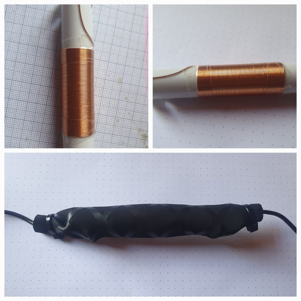
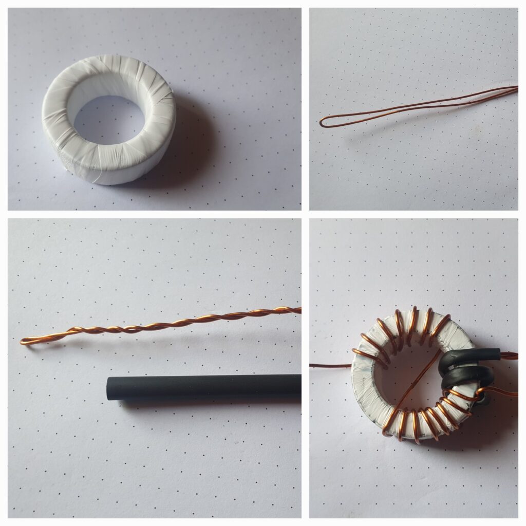
The inductor is made with about 10cm of the 16mm ISO Pipe. I drilled 4 holes (2 on each side) for the antenna wire. (Cut both antenna wires at least 5 cm longer!)
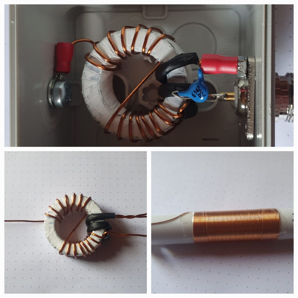
Now its time for the ferrite core. I used roughly 110cm from the 1mm enameled copper wire. Take about 16cm, bend it over and drill it together. After that you may want to use a little bit to better isolate the drilled part.
Now start to wind it arround the ferrite core as tightly as you can. I used teflon tape to protect the enameled copper wire from the sharp-edged ferrite core.
You could make a 1:49 version with 7 windings or you could try 1:64 with 8 windings. (You need about 15cm more of the copper wire!)
Take a close look to the pictures and the diagram of PD7MAA to wire everything correctly.
The next step ist to put it all together. Solder a ring cable lug on the cooper wire on the single side. This one will connect to the antenna wire. I used an M4 screw an an fitting ring cable lug for that.
Add a smaller ring cable lug on the other side on the drilled wires. This one will be connected with the base of the N-Socket (or PL-Socket) which I screwed with two M3 screws to the case.
The last wire goes to the center of the N-Socket (or PL-Socket). The last step is to add the capacitor. Solder one leg of the capacitor to the Base of the N-Socket (I used the ring cable lug for that because it was easier to solder) and the other leg to the center of the N-Socket (or PL-Socket).
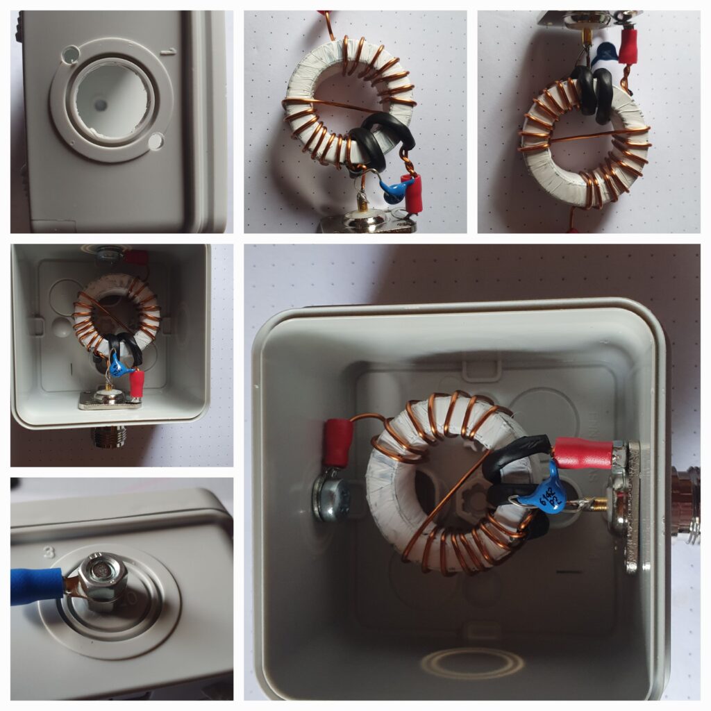
The last step ist to put everything into the case and screw it all together.
Tip: You can also try to add a second capacitor (or use 200pF). This will maybe increase your bandwith a little bit.
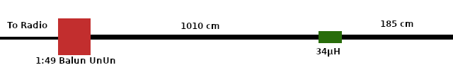
Do not solder (or crimp) the antenna wire now to the ring cable lug outside of the box. You have to cut the wires of the antenna at least 5cm longer than in the manual. 1015cm instead of 1010cm and 190 instead if 185cm.
You need to make some adjustments once the antenna is build up. First check the SWR on the higher bands. In this case 10m and 20m and cut (in 1cm or 50cm steps) the wire at the end by the box to correct the SWR on this bands.
Once you are happy with that you can also cut (in 1cm or 50cm steps) on the other end for the lower bands (here for the 40m band).
If everything is ok than you can solder (or crimp) the last ring cable lug.
Here are my measurements after the corrections:
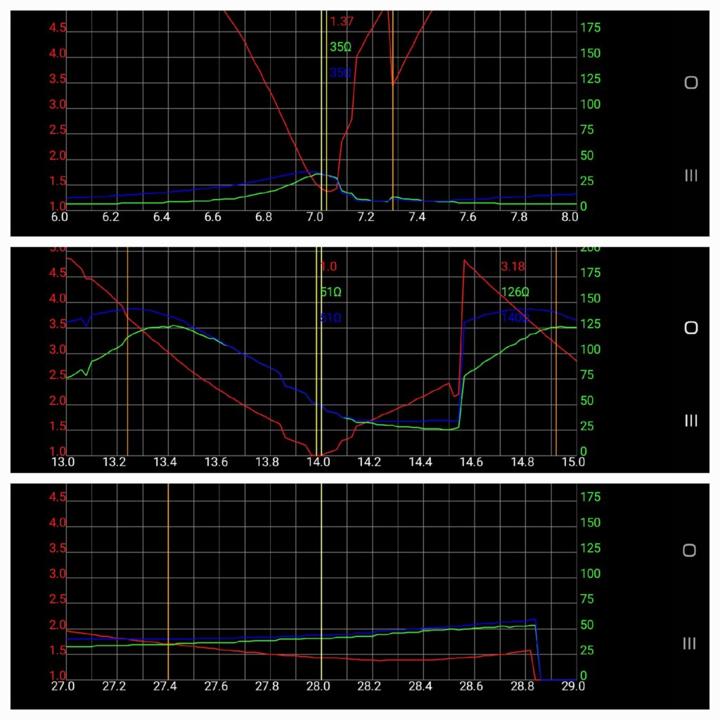
The antenna has a very small bandwith on the 40m band but I got an SWR of 1.5 on 40m. I have 1.7 on 10m and 1.07 on 20m. (There is also an SWR of 2.0 on 12m and it is possible to use other bands with a tuner)
You don’t have to hang up the wire in a straight line. I used an L-Form between the house and two trees.
Here is a Screenshot from https://pskreporter.info of my first test with FT8 on 20m:
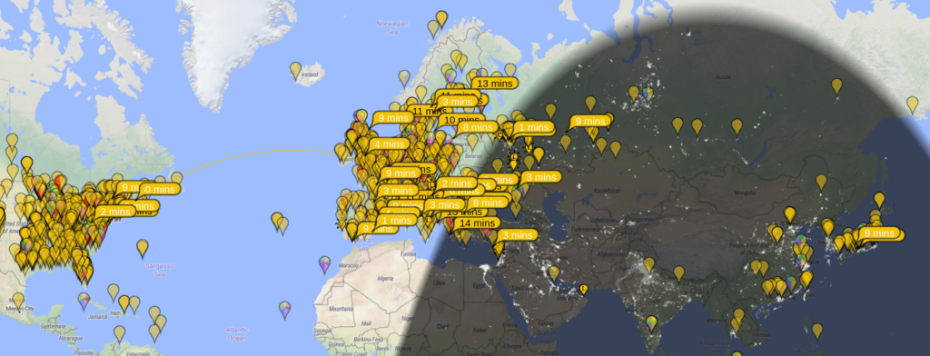
I used my Yeasu FT-817 with only 5 Watts.